 |
The
first step in construction of the motor mount started with the recovery
system hard points. Using a cad program I was able to make a layout template for the holes |
 |
| By laying the template directly onto the rings, I then
drilled both rings with the eight needed holes. |
 |
 |
|
|
| Once the holes were drilled I used a router and table
to cut a lip around the edge of the centering rings. This lip will seat
the coupler's edge. |
 |
|
|
|
| Next came the attachment of the "U-bolts". There would
be two attachment points for the sustainer recovery system. Note the large
fender washers used to distribute the load. |
 |
|
|
|
| The two centering rings were pulled together with some
1/4" all thread.
|
 |
|
|
|
Nuts and washers complete the assembly.
|
 |
|
|
|
|
The placement of the centering rings was critical. Again
a CAD system was used to ensure the correct placement of each ring.
|
|
|
|
Here are the rings shown positioned on the 98mm motor
tube. This tube is 41" long, giving me the capability of loading a N2000
motor in the future.
|
|
|
| Here is the dry assemble of the motor mount laying next
to the case for the M1939 motor. alongside of that is the main airframe
tube. This tube will run the entire length of the sustainer section. It
is designed to be the main strength tube and will be covered in 2 layers
of 10oz fiberglass. An 11.41" body tube will be on the outside of that.
|
 |
|
|
|
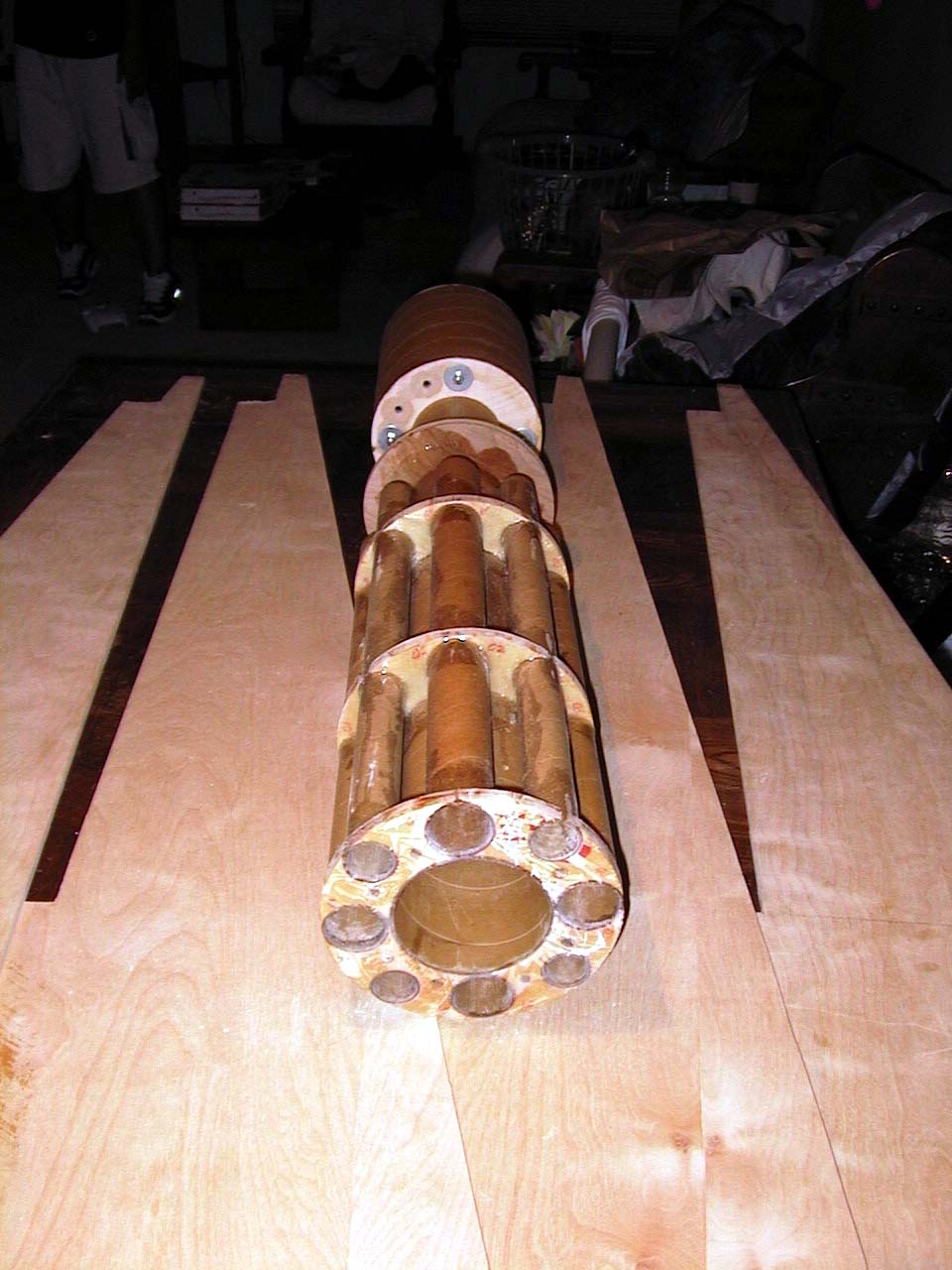
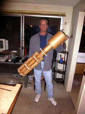
| Here is the completed
motor mount assembly. It's bigger than I thought. Looking at the aft
end, you can see the main 98 mm central motor, up to an N2000. Surrounding
that are the four 38 mm tubes for the outboards, up to J570s. The other surrounding
smaller holes are the guide tubes for the interstage coupler. Four
1.25" wooden dowels will slide up from the booster stage into the
sustainer.
|
 |
|