| |
|
| Coupler Idea |
|
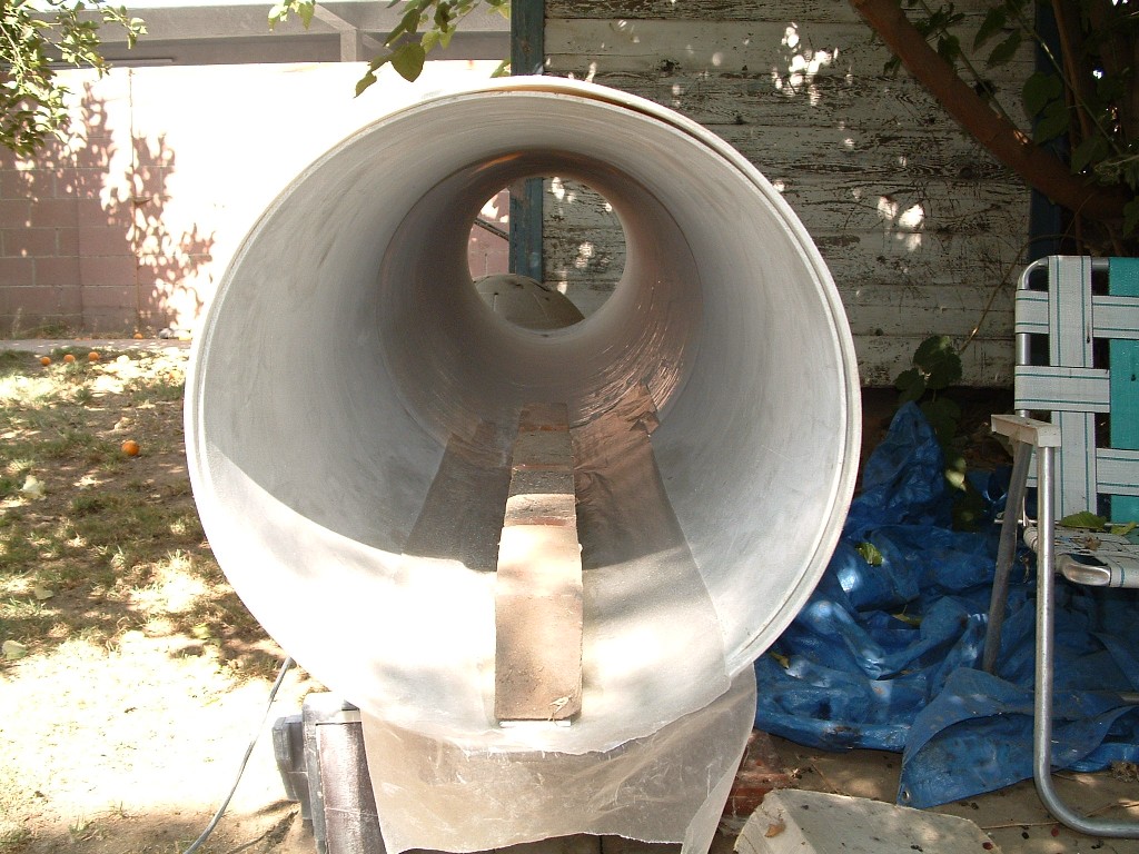
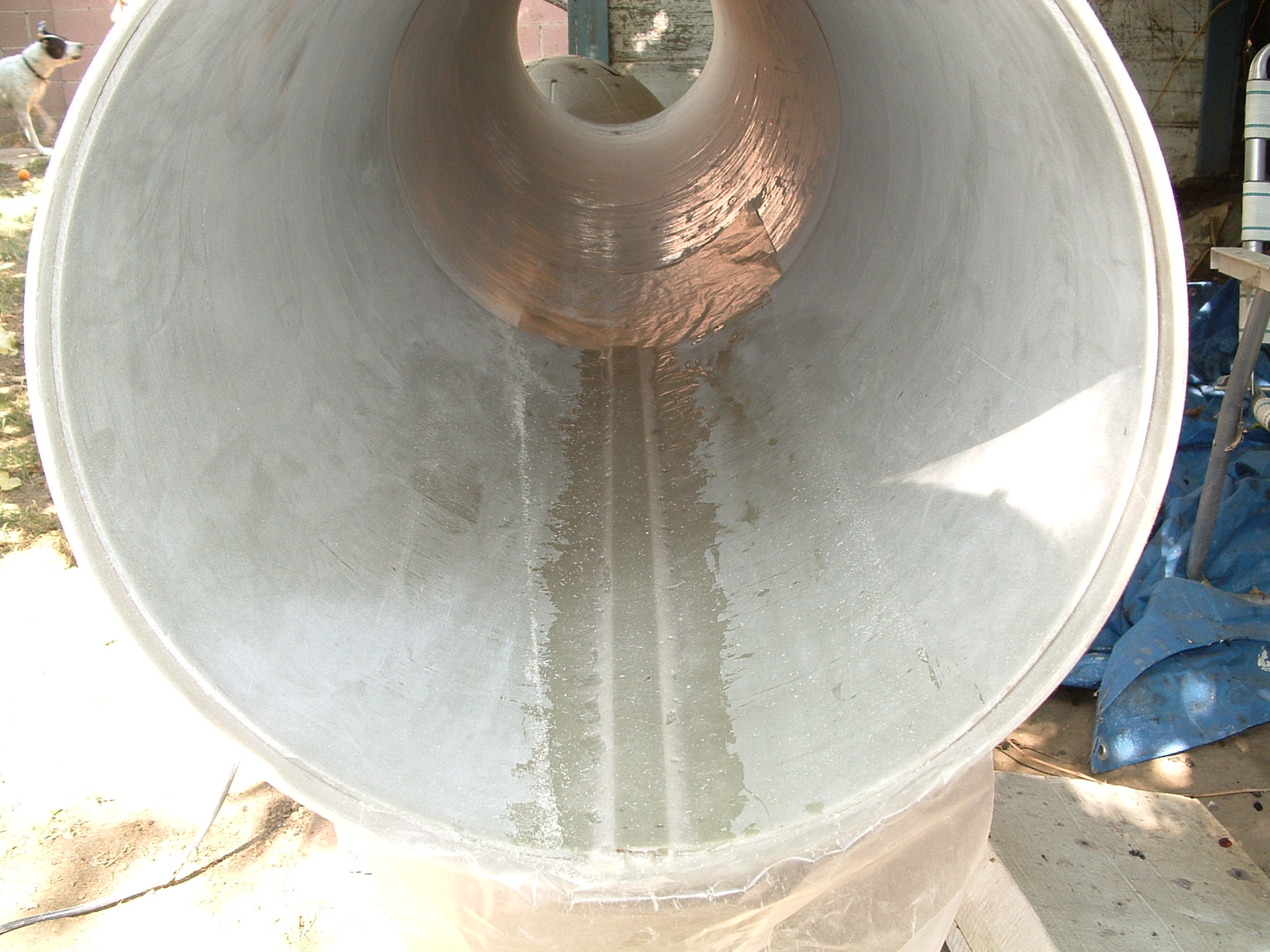
 | The main coupler needs to be the stiffest section of the entire
airframe. This design represents the most overbuilt section of the
entire rocket. |
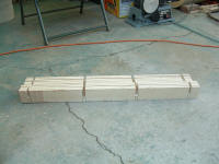
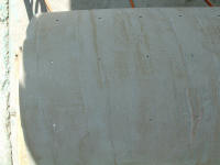
| 36" (was
48") was split down the middle and about 1" was removed. |
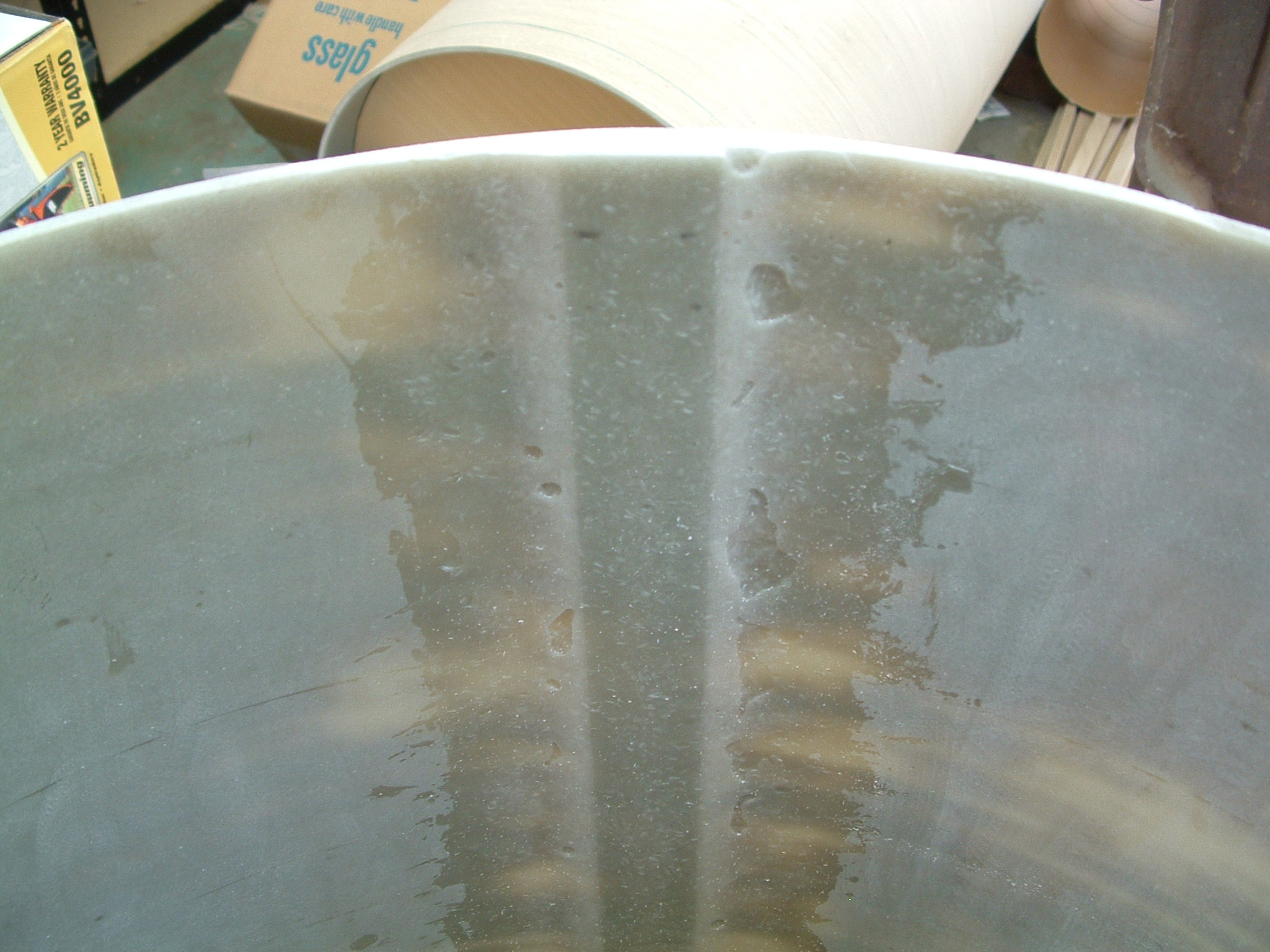
| A combination of wax paper, epoxy, chopped fibers, 2" X 36" aluminum
and four bricks were used to join the two halves together. |
| This could have been enough right here. |
|
   |
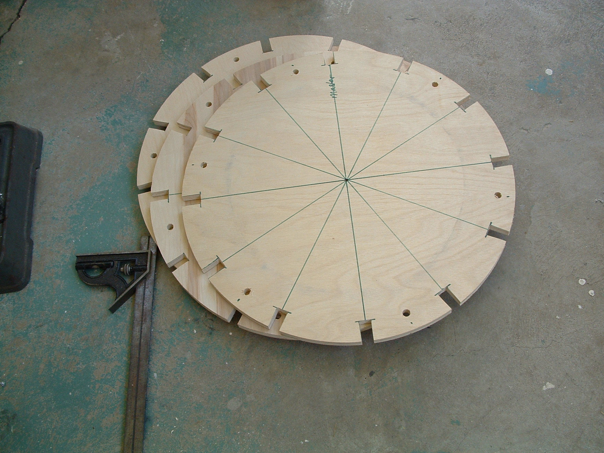
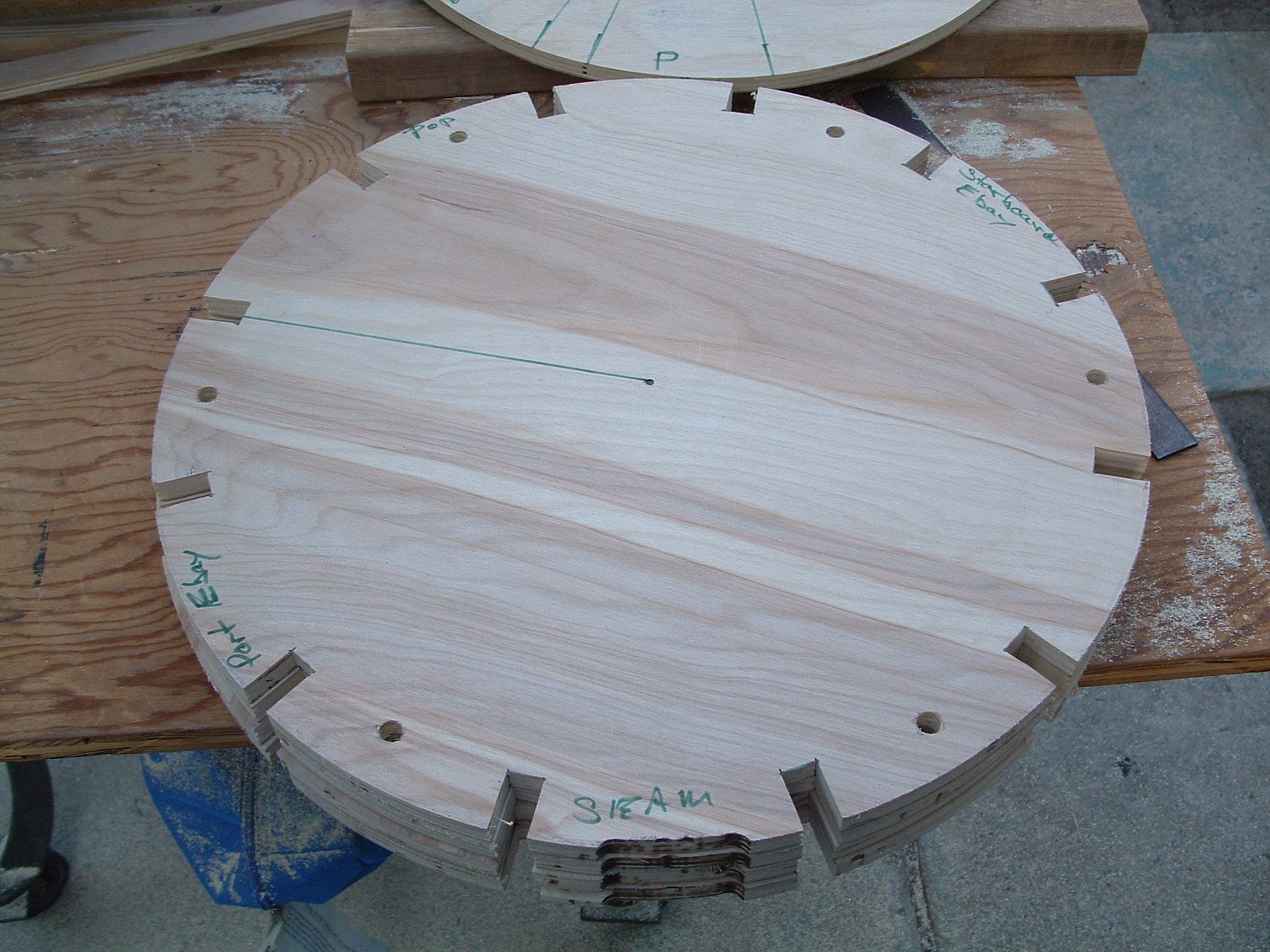
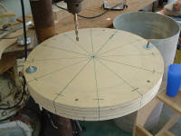
Centering Rings
|
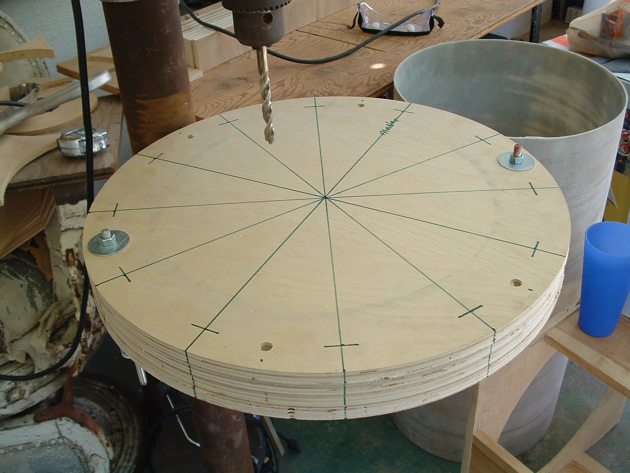
|
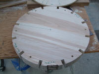
| Four centering rings were cut from 1/2" Birch plywood and drilled in
six places for the connecting all thread. |
| At this point I think there's more than enough strength in the
coupler. |
|
  |
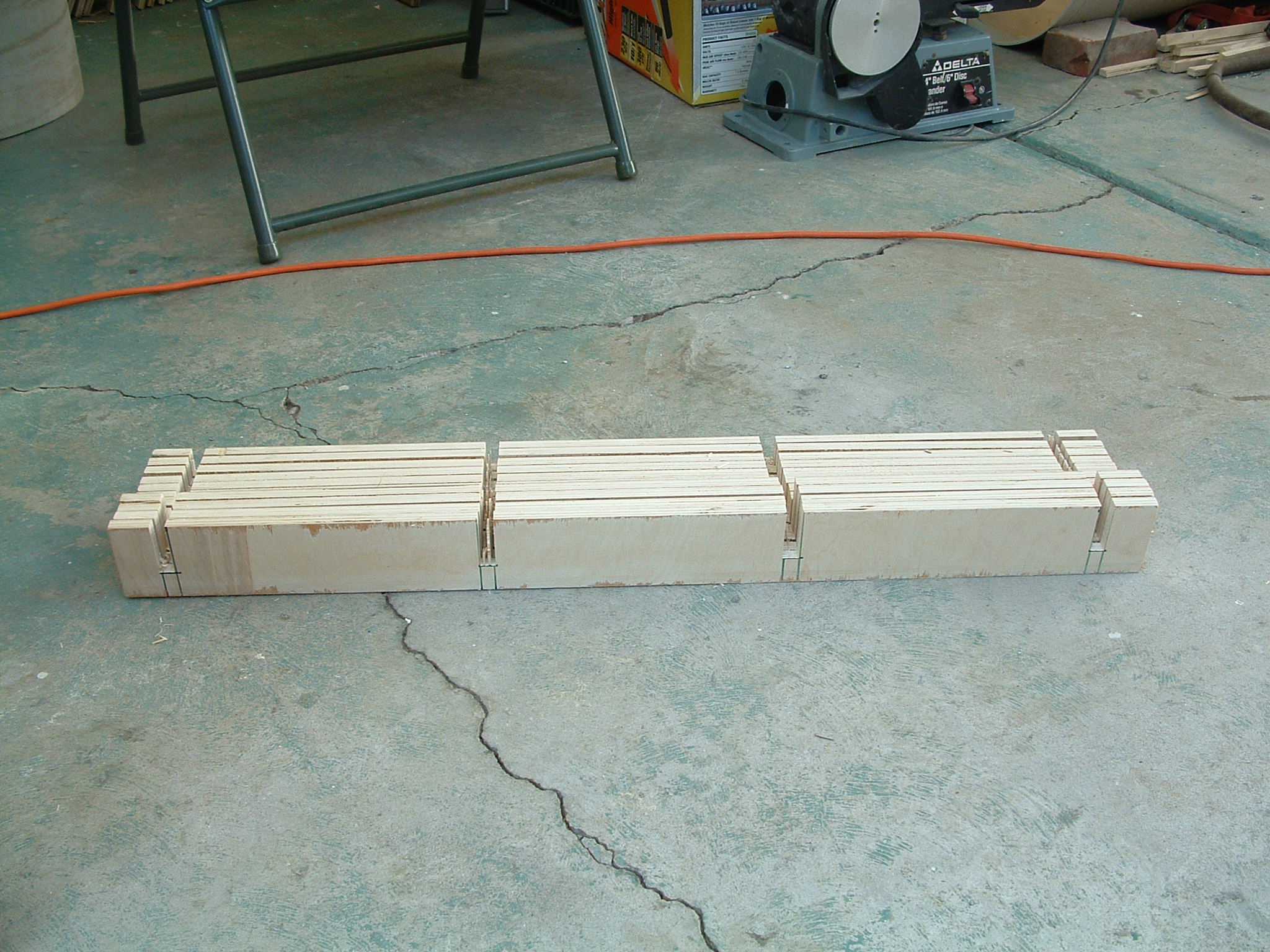
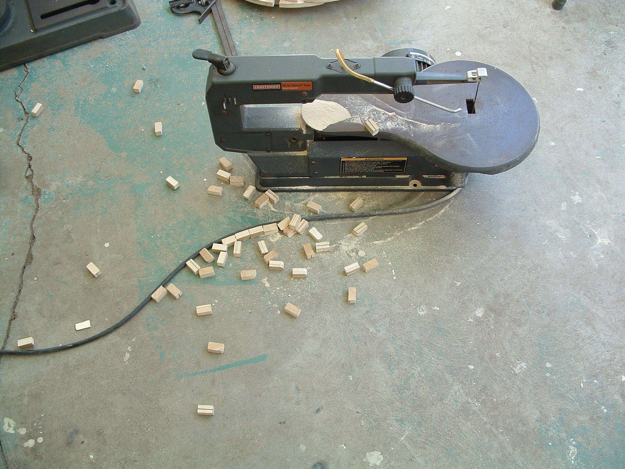
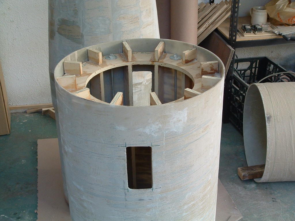
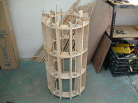
| Ribs & Rings |
|
| 12 ribs were cut from 1/2" plywood. |
| 4 ribs were 3" wide to form the electronics bays, and the 8 others
were cut 2" wide. |
| The rings were notched to accept each rib and the ribs were notched
too. |
| That's a lot of notches. |
|
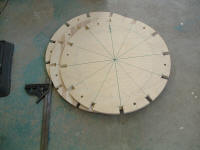   |
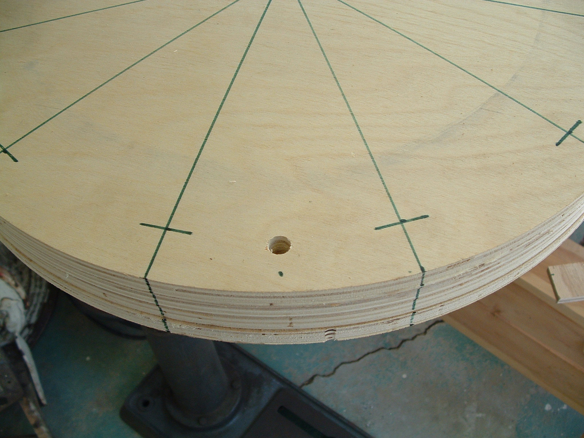
| Seam Relief |
|
| In order to accommodate the seam of the coupler tube, another notch
was cut from the edge of each ring. |
| Here's all four of them ready to go. |
|
 |
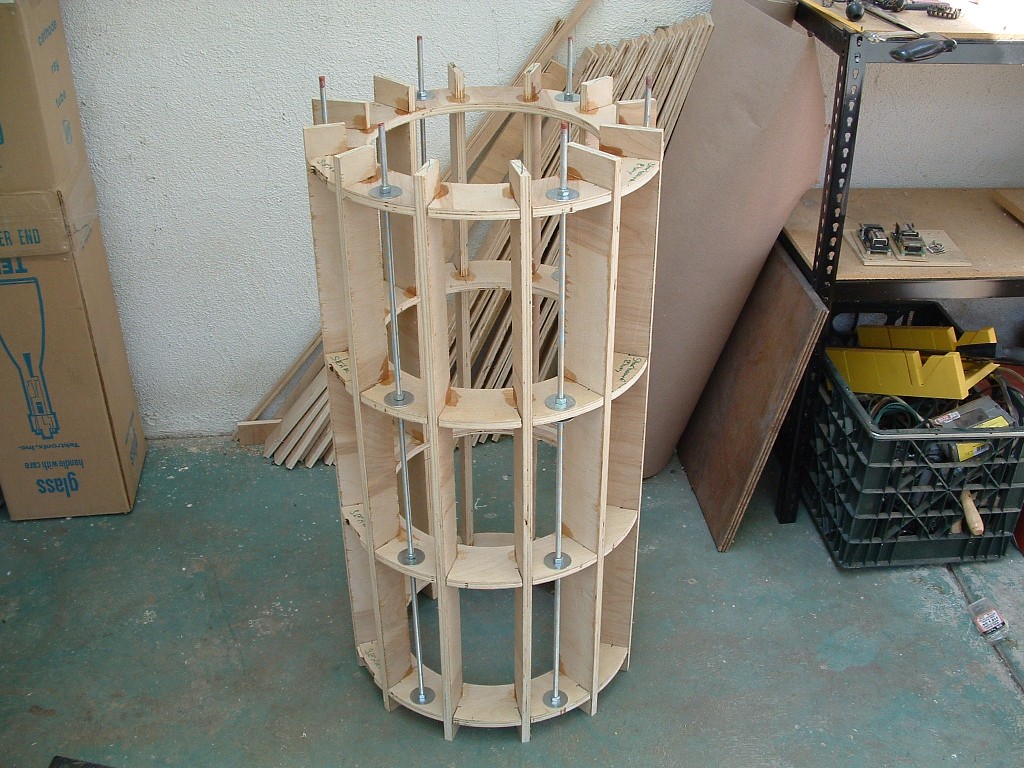
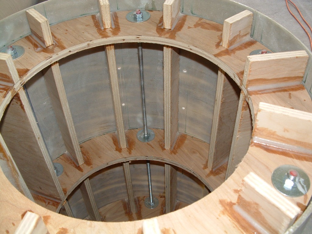
| Assembly |
|
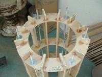
| The ribs, rings, and all-thread were assembled an the ribs tacked to
the rings with large dabs of epoxy. |
| After this had setup the final filleting of all joints was done. |
| 12 ribs, four rings, two sides each that makes for 96 fillets. |
|
   |
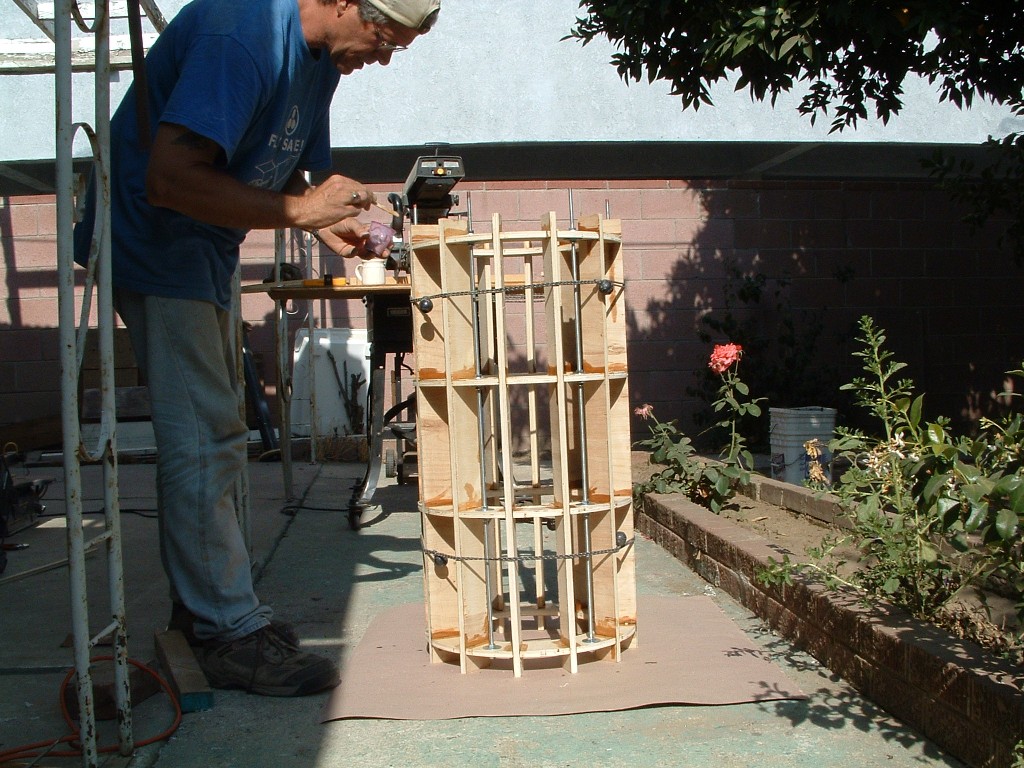
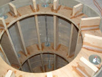
| Electronics Bay |
|
| The main coupler will also house the primary and backup electronics. |
| The first step was to cut out the holes for electronics in the coupler
section. |
|
  |
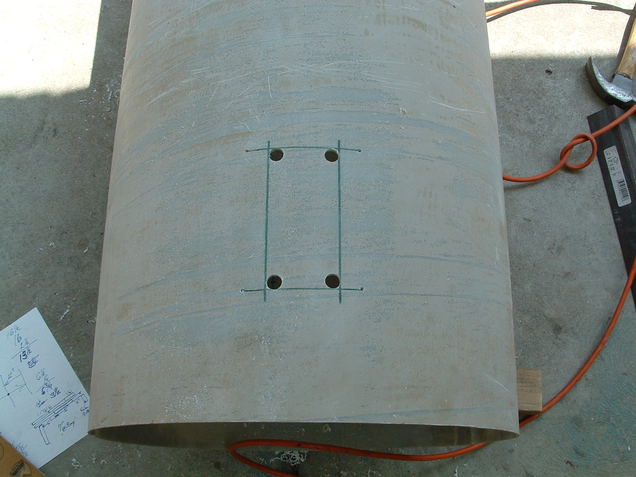
| Lower Section |
|
| The forward part of the main coupler will be epoxied into the payload
section of body tube. |
| The aft section will be secured to the booster via nuts and bolts. |
| 12 rows of 5 holes were original designed to allow 2" wood screw to
hit each of the ribs. Due to some shifting while the epoxy cured,
this plan was changed. |
| Attachment to the booster section will now be done via nuts and bolts. |
|
  |